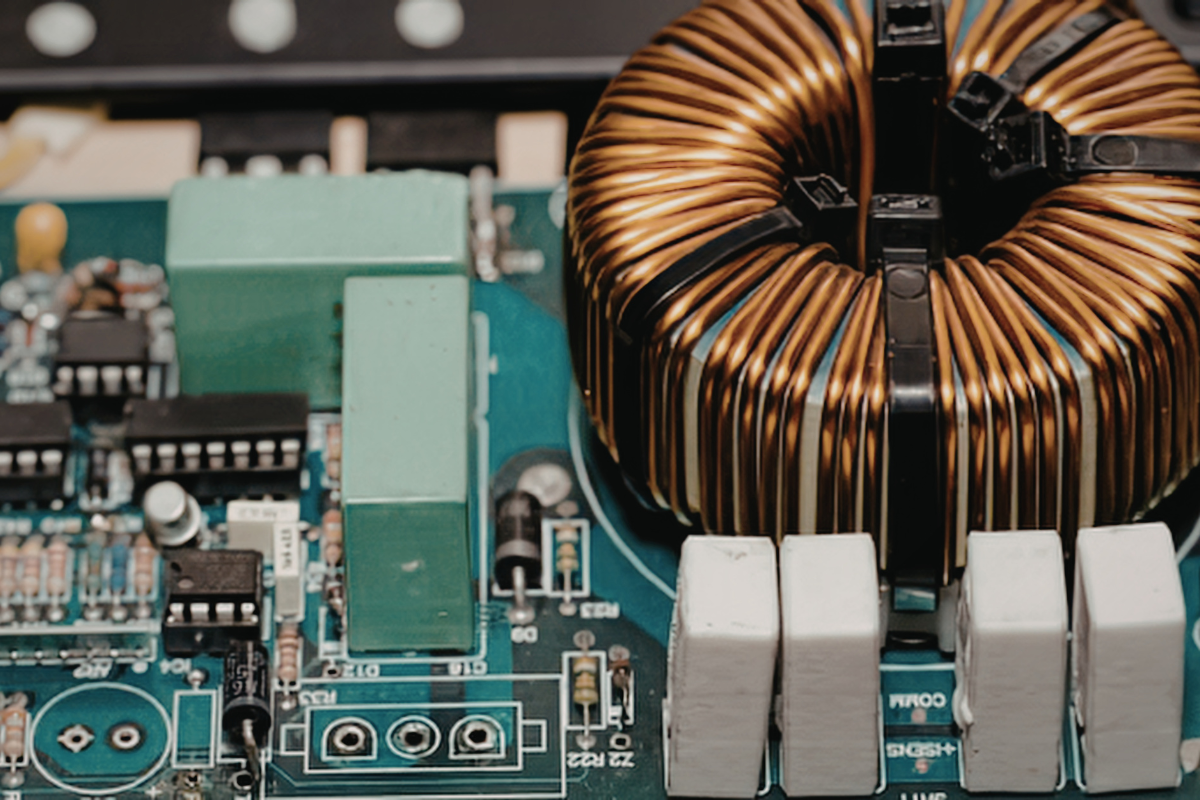
Every circuit board has two layers of anatomy: the board itself, and the circuit board components mounted on it. The board is the structure, built from layers of insulating material and copper that carry power and signals. The components do the work: resistors, capacitors, integrated circuits, connectors, and more.
This guide covers both. You’ll learn what each part of a circuit board does, how to identify components by their reference designators, and how component choices affect the way a board is assembled, inspected and tested. Whether you’re an engineer reviewing a design, a buyer comparing quotes, or new to electronics, bookmark this article as a practical reference.
What Is a Circuit Board?
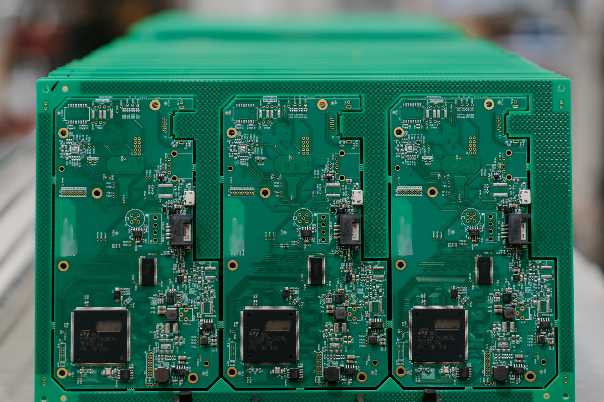
A printed circuit board (PCB) is a flat board made of insulating material with copper pathways bonded to it. Those pathways, called traces, connect electronic components so that electricity flows between them in a controlled, repeatable way.
Circuit boards go by several names. You’ll hear PC board, printed wiring board (PWB) and, especially in defence and aerospace, printed circuit card. Once components are soldered onto the board, it becomes a printed circuit board assembly (PCBA), also called a circuit card assembly (CCA).
PCB vs. PCBA: What’s the Difference?
- PCB (bare board): The substrate, copper, solder mask and silkscreen, with no components attached. It can conduct electricity, but it can’t do anything yet.
- PCBA (assembled board): The bare board with components placed and soldered. This is the working part that goes into a product.
The distinction matters when you’re sourcing. Building a circuit board happens in two stages: fabrication produces the bare board, and assembly turns it into a working part. Assembly, which covers placing components, soldering, inspection and testing, is the core of what an electronics manufacturing services (EMS) provider like IMS does. Learn more about how this fits into a complete product in our guide to box build vs. PCB assembly.
Parts of a Circuit Board
Before a single component is placed, a bare board already has several distinct parts. Each one affects how the finished assembly performs and how reliably it can be built.
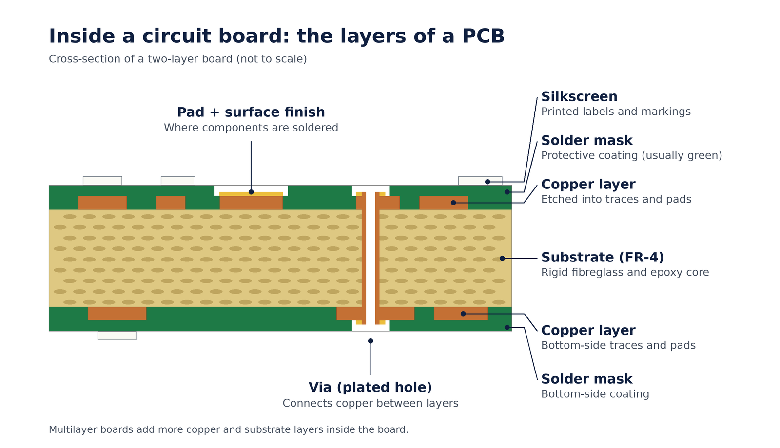
Substrate
The substrate is the board’s rigid core. The most common material is FR-4, a woven fibreglass cloth bonded with flame-retardant epoxy resin (the “FR” stands for flame retardant). FR-4 is strong, a good electrical insulator, and cost-effective. Boards that face high heat or high frequencies may use specialty materials such as polyimide, ceramic or high-frequency laminates.
Copper Layers
Thin sheets of copper are laminated to one or both sides of the substrate, and to internal layers on multilayer boards. Copper thickness is usually specified by weight, such as 1 oz copper (about 35 microns thick). Heavier copper carries more current and helps with heat.
Traces
Traces are the copper “wires” left behind after unwanted copper is etched away. Their width and spacing are designed around the current they carry and the signals they move. Power traces tend to be wide; signal traces can be very fine.
Pads
Pads are the exposed copper areas where component leads or terminals are soldered. Their size and shape must match the component package. Pad design is one of the most common sources of assembly defects when it’s wrong.
Vias and Plated Through-Holes
Vias are small plated holes that connect traces on different layers. Plated through-holes are larger holes that accept the leads of through-hole components. Multilayer and high-density boards may also use blind vias (visible on one side only), buried vias (hidden between internal layers) and microvias.
Solder Mask
Silkscreen
The silkscreen is the printed legend on top of the solder mask. It shows reference designators (such as R1 or C12), polarity marks, pin 1 indicators, logos and part numbers. Technicians rely on it during assembly, inspection, rework and field repair.
Surface Finish
Exposed copper pads are coated with a surface finish to protect them and make them easy to solder. Common finishes include HASL (hot air solder levelling), ENIG (electroless nickel immersion gold), OSP (organic solderability preservative), immersion silver and immersion tin. The right choice depends on the components, shelf life, and whether the design uses fine-pitch parts that need a very flat surface.
Fiducials, Test Points and Mounting Holes
- Fiducials are small copper alignment marks that automated pick-and-place machines use to locate the board precisely.
- Test points give test probes a place to make contact during electrical testing.
- Mounting holes secure the board inside its enclosure.
Circuit Board Components and What They Do
Circuit board components fall into two broad groups:
- Passive components such as resistors, capacitors and inductors. They store, filter or limit energy but can’t amplify a signal.
- Active components such as transistors and integrated circuits. They control the flow of current and need a power source to work.
Here are the components you’ll find on most boards, along with the letter used to identify each one in the silkscreen and schematic.
Resistors (R)
Resistors limit the flow of current and set voltage levels so other components aren’t overloaded. Surface-mount resistors are tiny rectangular chips, often black with a printed value code. Through-hole resistors are cylindrical with coloured bands that indicate resistance.
Capacitors (C)
Inductors (L) and Ferrite Beads (FB)
Inductors store energy in a magnetic field. They’re used in power supplies and filters to smooth current and block unwanted high-frequency signals. Ferrite beads are a close relative that suppress high-frequency noise on power and signal lines.
Diodes and LEDs (D)
Diodes let current flow in one direction only. They protect circuits from reverse polarity, convert AC to DC, and clamp voltage spikes. Light-emitting diodes (LEDs) are diodes that emit light, typically used as status indicators. Diodes are polarized; a band or marking shows the cathode side.
Transistors (Q)
Transistors act as electronic switches or amplifiers. Common types include bipolar junction transistors (NPN and PNP) and MOSFETs. On industrial and power boards, MOSFETs often switch motors, heaters and other loads.
Integrated Circuits (U)
Integrated circuits (ICs) are chips that package many transistors and other elements into one component. They range from simple logic gates and voltage regulators to microcontrollers, memory and processors. ICs come in many packages, from leaded SOICs to ball grid arrays (BGAs) with hundreds of connections hidden underneath the part.
Crystals and Oscillators (Y)
Crystals and oscillators generate precise timing signals. Microcontrollers, communication interfaces and real-time clocks depend on them to keep operations synchronized.
Transformers (T)
Transformers transfer energy between circuits while stepping voltage up or down. They also provide electrical isolation between sections of a circuit, which protects both equipment and users.
Relays (K)
Relays are electrically operated switches. A small control signal can switch a much larger load, which makes relays common in industrial control, automation and power distribution equipment.
Connectors (J and P)
Connectors link the board to cables, other boards, power and the outside world. Connector selection and placement have a big impact on serviceability in the field. If your product connects to custom harnesses, see our cable assembly guide.
Switches (SW)
Switches let users or technicians open and close a circuit manually. Examples include push buttons, toggles and DIP switches used for configuration settings.
Fuses (F)
Fuses protect the circuit by breaking the connection if current rises above a safe level. Some are replaceable; others are resettable polymer fuses.
Sensors
Sensors convert physical conditions, such as temperature, pressure, light or motion, into electrical signals the circuit can read. Their designators vary depending on the type, and many are packaged as integrated circuits.
How to Identify Components on a Circuit Board
The fastest way to identify a component is by its reference designator: the letter-and-number label printed in the silkscreen beside it. The letter tells you the component type, and the number identifies that specific part. That designator also links the part to the bill of materials (BOM), which lists the exact part number, value and manufacturer.
| Designator | Component | What it does | How to spot it |
|---|---|---|---|
| R | Resistor | Limits current; sets voltage levels | Small rectangular chip or banded cylinder |
| C | Capacitor | Stores energy, filters noise | Small chip near ICs, or a cylinder (electrolytic) |
| L | Inductor | Smooths current, filters signals | Wire coil or square shielded block |
| FB | Ferrite bead | Suppresses high-frequency noise | Small chip, often on power lines |
| D | Diode or LED | One-way current flow, indicator light | Marked with a band on the cathode side |
| Q | Transistor | Switches or amplifies signals | Three-terminal package, such as SOT-23 or TO-220 |
| U | Integrated circuit | Logic, control, processing, regulation | Multi-pin chip with a pin 1 marker |
| Y | Crystal or oscillator | Generates timing signals | Small metal can or ceramic package |
| T | Transformer | Steps voltage, provides isolation | Larger wound component |
| K | Relay | Switches a larger load with a small signal | Rectangular box, often through-hole |
| J / P | Connector | Links to cables, power or other boards | Headers, sockets, terminal blocks |
| SW | Switch | Manual on/off or configuration | Buttons, toggles, DIP switches |
| F | Fuse | Overcurrent protection | Small chip or cartridge |
| TP | Test point | Probe access for testing | Exposed pad or loop |
Look for other silkscreen clues too. Polarity marks show which way diodes and electrolytic capacitors face, and a dot or notch marks pin 1 on ICs. Getting these right is a basic part of every quality inspection.
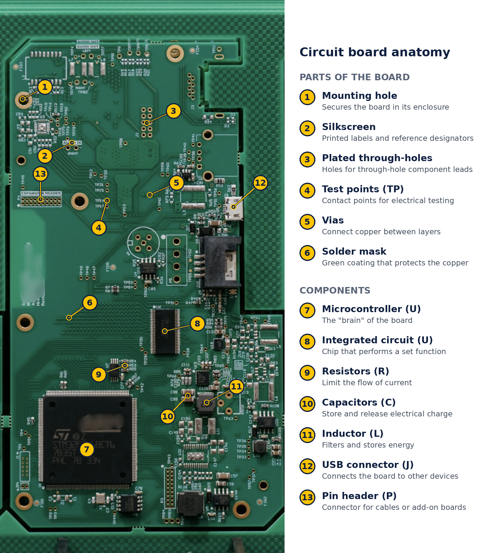
Parts and components of a circuit board assembled at IMS in Calgary. Letters in brackets are the reference designators printed on the board.
Surface Mount vs. Through-Hole Components
Components attach to a circuit board in one of two ways:
- Surface mount technology (SMT): Components sit directly on pads on the board’s surface. SMT parts are small, can be placed at high speed by automated machines, and allow dense, compact designs. Common packages include chip resistors and capacitors (such as 0402 and 0603 sizes), SOT-23 transistors, SOIC and QFN chips, and BGAs.
- Through-hole technology (THT): Component leads pass through plated holes and are soldered on the opposite side. Through-hole parts create a stronger mechanical bond, which makes them a good fit for connectors, large capacitors, transformers and components exposed to vibration.
Many boards use both. For a deeper look at choosing between them, especially for rugged applications, read SMT vs. THT: Choosing the Right Process for Rugged Applications.
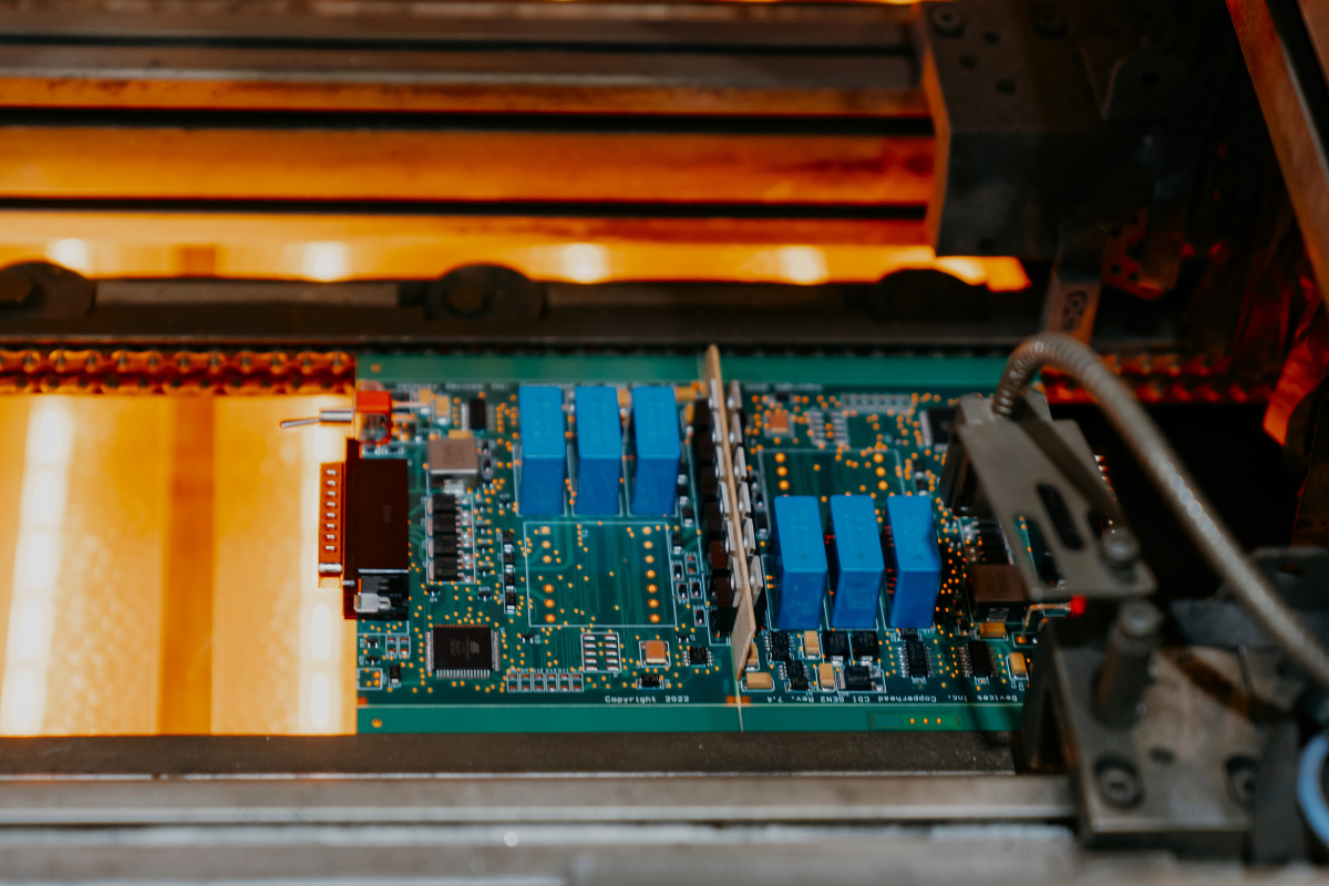
Selective soldering of through-hole components at IMS in Calgary.
How Component Choices Affect Manufacturing
The components on a circuit board don’t just determine what the product does. They also shape how the board is built, inspected and tested, and that affects cost, lead time and reliability.
- Smaller packages need tighter process control. Tiny chip components and fine-pitch ICs depend on precise solder paste deposits. That’s why IMS uses in-line solder paste inspection (SPI) and 3D automated optical inspection (AOI) to catch problems before they become defects.
- Hidden solder joints need X-ray inspection. BGAs and QFNs have connections underneath the component body that can’t be seen from above. IMS uses Glenbrook X-ray inspection to verify these joints.
- Mixed technology adds process steps. A board with both SMT and through-hole parts may need selective soldering or hand soldering after the SMT process.
- Component availability affects lead times. A single hard-to-source IC can hold up an entire build. Planning for alternates early helps. See our guide to component obsolescence planning.
- The operating environment matters. Boards headed for oil and gas, mining or military use may need conformal coating or potting to protect components from moisture, vibration and contaminants. Learn more about potting electronics for harsh environments.
- The quality class sets the inspection standard. IPC Class 2 and Class 3 define different acceptance criteria for solder joints and workmanship. Read IPC Class 2 vs. Class 3 explained.
A design for manufacturability (DFM) review before production is the best way to catch component and layout choices that could add cost or risk. Here’s how DFM reduces manufacturing costs.
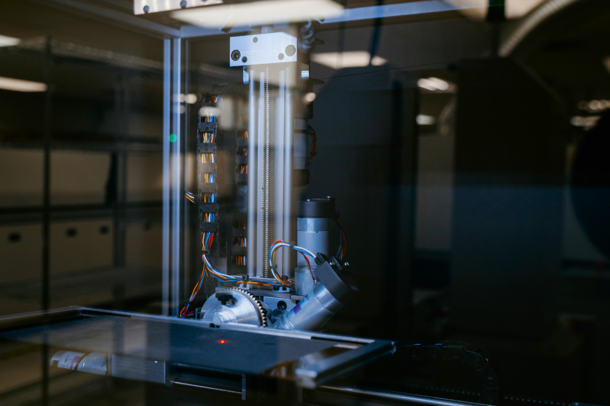
Relays are electrically operated switches. A small control signal can switch a much larger load, which makes relays common in industrial control, automation and power distribution equipment.
Types of Circuit Boards
Circuit boards are also grouped by how many copper layers they have:
- Single-sided boards have copper on one side. They’re simple and low cost, and suited to basic electronics.
- Double-sided boards have copper on both sides, connected by plated holes. They’re common in industrial controls, power supplies and instrumentation.
- Multilayer boards stack four or more copper layers with insulation between them. They support complex, compact designs in aerospace, telecommunications, defence and computing.
Boards can also be rigid, flexible or rigid-flex, which combines both in one assembly. For the design side, including layout and terminology, read the basics of PCB design.
Frequently Asked Questions
What are the main parts of a circuit board?
A bare circuit board is made up of the substrate (usually FR-4), copper layers, traces, pads, vias, solder mask, silkscreen and a surface finish. Once assembled, it also includes the circuit board components soldered onto it, such as resistors, capacitors, integrated circuits and connectors.
What’s the difference between a PCB and a PCBA?
A PCB is the bare board with no components. A PCBA, or printed circuit board assembly, is the board after components have been placed and soldered, making it a working part of a product.
What is a circuit board made of?
Most circuit boards are made of FR-4, a fibreglass and epoxy laminate, with copper layers for the circuitry. A solder mask coating protects the copper, and a silkscreen layer adds labels.
How do you identify components on a circuit board?
Check the reference designator printed beside each component. The letter identifies the type (R for resistor, C for capacitor, U for integrated circuit, and so on) and the number identifies the specific part. The designator matches an entry in the bill of materials, which lists the exact part number.
Why are most circuit boards green?
The green colour comes from the solder mask. Green became the industry standard and offers good contrast for visual and automated inspection, but solder mask is also available in other colours, such as blue, red, black and white.
What is a printed circuit card?
A printed circuit card is another name for a printed circuit board, commonly used in defence and aerospace. An assembled card is often called a circuit card assembly (CCA).
Build Your Next Circuit Board Assembly With IMS
Understanding the anatomy of a circuit board makes it easier to design better products, ask sharper questions and compare manufacturing partners with confidence.
IMS has been assembling circuit boards in Calgary for more than 20 years for industries including oil and gas, military and defence, transportation, telecommunications and industrial automation. We build to IPC Class 2 and Class 3 standards under an ISO 9001:2015 quality system, with in-line SPI, 3D AOI and X-ray inspection, BGA and fine-pitch rework, and functional testing on request.
Have your BOM and design files ready? Here’s how to prepare an RFQ for an accurate quote, or contact our team to talk about your next build. Explore our full circuit board assembly services.