
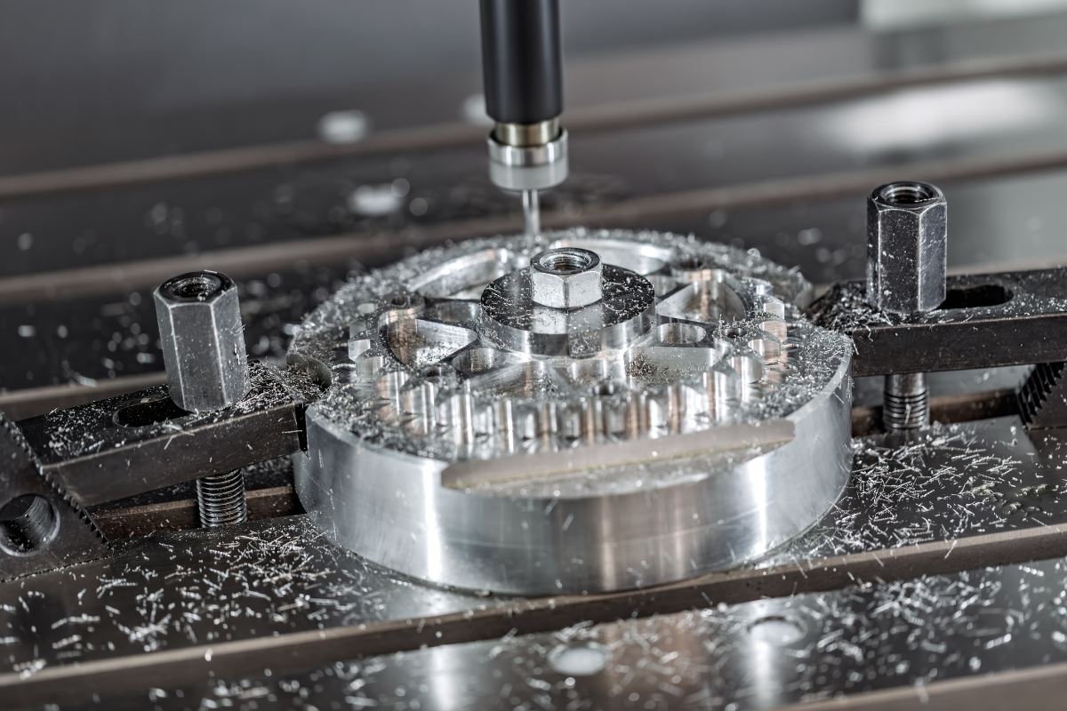
Aluminum milling costs depend on more than the price of the metal. A tight pocket corner, a deep slot, or unnecessary tolerance can make a straightforward part harder to produce. The best opportunity to address those costs is while the design is still being developed.
For OEMs designing mounting plates, brackets or electronics housings, the goal is to keep useful features while making them easier to machine without compromising fit or function. Start with these seven drawing-level checks before requesting a quote.
What Is Aluminum Milling?
Aluminum milling is a CNC machining process in which a rotating cutting tool removes material from an aluminum workpiece to create features such as pockets, holes and profiles. Unlike turning, where the workpiece rotates, milling uses a rotating cutter to produce the required geometry.
This article assumes you have already chosen a milled part. If you are still deciding how to make an enclosure, start with our comparison of sheet metal fabrication versus CNC machining.
Give Internal Corners Room for the Cutter
A round milling cutter leaves a radius in an internal pocket corner. Specifying a very small radius can require a smaller tool and additional machining time, while a larger radius may allow a more productive toolpath.
Check what actually needs to fit inside the pocket. If a rectangular component needs corner clearance, ask whether a local corner relief would work instead of tightening every pocket radius. Keep that relief away from sealing surfaces or other functional features.
For example, consider a 12 mm-deep pocket with a 2 mm internal corner radius. If the mating part allows it, increasing the radius to 5 mm could give the machinist more tooling options. These are illustrative dimensions, not universal design limits or IMS tooling specifications.
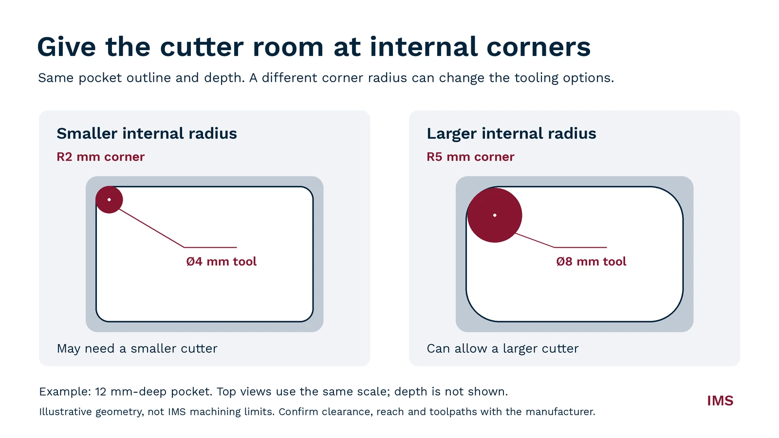
A larger internal corner radius can allow a larger cutter when the mating part permits. Dimensions are illustrative, not IMS machining limits.
Review Deep Pockets and Narrow Slots
Depth becomes more difficult when the cutter must reach through a narrow opening. A long, slender tool is less rigid than a shorter one, and deep features also complicate chip removal. Before adding a deep cavity, check whether the full depth is necessary throughout.
For an electronics housing, that might mean keeping a local recess beneath a connector rather than deepening the entire pocket. Another option is a through-feature where the product’s sealing and assembly requirements permit it. Ask the manufacturer to review depth, width and access together rather than treating each dimension separately.
Keep Thin Walls and Floors Stable
Removing material can reduce weight, but thin sections can flex or vibrate during machining. Tall, unsupported walls and thin pocket floors deserve particular attention. Their suitability depends on the geometry and how the part will be supported.
If a housing wall is not constrained by a connector or mating component, consider whether it can be thicker. A rib or local support may also help, provided it does not create a harder-to-reach pocket. Discuss the trade-off before applying a single minimum wall thickness across the design.
Specify Holes and Threads for Their Job
Choose standard hole and thread sizes where the assembly allows, and distinguish a clearance hole from a precision locating bore. They have different jobs and should not automatically receive the same requirements. Hole-making method and tooling can then be selected around the actual fit.
For a blind threaded hole, show the required usable thread depth separately from the drilled depth. Do not assume the thread must run to the bottom of the hole. Thread engagement should be determined from the joint’s load, fastener and material requirements, not a blanket rule.
For example, a screw securing a lightweight cover does not necessarily need the same engagement as a fastener carrying a structural load. Tell the manufacturer which function the joint serves so the feature can be reviewed in context.
Plan for Tool Access and Workholding
Every feature needs a cutting approach, and the workpiece needs to be held securely while that feature is machined. Holes on several faces, hidden recesses and awkward clamping surfaces can add setups or fixturing. Review those features together before finalizing the part.
On a mounting plate, could an accessible through-hole replace a blind hole approached from the opposite face? On a housing, could mounting features share an approach direction? Keep alignment and service access intact; reducing setup count is only useful if the part still works.
Put Tight Tolerances Where They Matter
Some features need close control, including locating bores and mating interfaces. Others may not. Applying the tightest tolerance to every dimension can add machining and inspection work without improving the assembly.
Identify functional datums and the dimensions that control how components fit together. For example, the location of a mounting-hole pattern may matter more than the outside profile of a concealed bracket. Use an agreed general tolerance for non-critical features rather than leaving 0their acceptance criteria unclear.
The aim is not to loosen every tolerance. It is to make the drawing reflect the product’s actual requirements so manufacturing effort goes where it is needed.
Choose the Alloy and Finish Before Release
“Aluminum” alone is not a complete material specification. Identify the alloy and temper required by the application, and ask about suitable stock availability before freezing the dimensions. If alternatives are acceptable, make that an explicit engineering decision rather than an assumed substitution.
Include the finish in the design review, too. Anodizing changes dimensions because its oxide layer grows into and out of the aluminum surface, so precision fits may need an allowance. State whether critical dimensions apply before or after finishing.
For an electronics housing, flag any electrical contact areas that must remain conductive and discuss the appropriate treatment. Specify cosmetic requirements only on surfaces that need them. This gives the manufacturer a clearer picture of both the mechanical and electrical requirements.
Aluminum Milling Checklist Before You Request a Quote
Before sending the files, check that the package includes:
- Matching revisions: A 3D CAD model and drawing that describe the same part.
- Material: The required alloy, temper and any permitted alternatives.
- Functional requirements: Critical fits, datums, tolerances and surface requirements.
- Feature details: Internal radii, hole specifications and usable thread depths.
- Finishing: The finish specification, protected areas and final dimensional requirements.
- Production context: Order quantity, expected repeat demand and assembly information.
Highlight anything still open to change. A note such as “pocket corner radius may increase if the mating component still clears” gives the manufacturer a useful option without authorizing an uncontrolled redesign.
Discuss Your Aluminum Part with IMS
IMS’s Calgary facility includes a Haas VF-2SS vertical CNC machining centre, alongside metal-cutting and turning equipment. The team can assess aluminum machining projects based on the material, geometry, tooling, tolerances and production requirements. Learn more about IMS’s in-house CNC machining capabilities.
Share your CAD files, drawings, quantity and assembly requirements with IMS before releasing the design. Contact the IMS team to discuss your part and request a quote.