Electrical performance is table stakes. For service-minded OEMs, cable assembly design also drives Mean Time to Repair (MTTR), first-time fix rate, and warranty cost. Every miswired connector or stressed termination is a second service event waiting to happen, and many intermittent faults trace back to poor routing or weak strain relief rather than a bad component. Most of those problems aren’t created in the field. They can be avoided at the design stage, when connector types, routing, and labelling get locked in.
Connector Selection and Placement
The connectors you choose, and where you put them, set the tone for how serviceable the whole assembly will be.
- Match connectors to service frequency. Use connectors rated for repeated mating cycles wherever a harness will be opened often (sensor harnesses, communication drops, and power distribution), and reserve sealed-for-life connections for sections that should rarely be touched.
- Place frequently disconnected connectors near access panels, not buried behind boards or structural members, with enough clearance for gloved hands and standard tools.
- Use keyed or polarized connectors to prevent mismating and reverse insertion, two of the most common sources of field failures and callbacks.
- Standardize on a limited set of connector families across products to simplify spares, training, and troubleshooting.
Routing, Strain Relief, and Service Loops
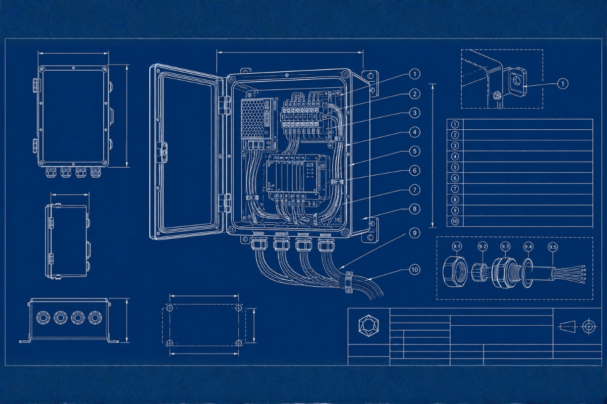
How a harness is routed and secured inside the enclosure has a direct impact on both reliability and service time.
- Use channels, clips, or tie points to keep cables on a predictable path instead of draped across boards or structural members.
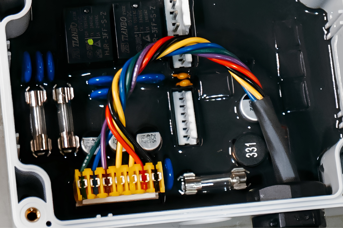
- Build in strain relief at entry points and connectors, so terminations aren’t stressed every time a panel opens or a cable gets tugged. This is where cracked solder joints and loose crimps usually begin.
- Leave enough slack for doors and panels to open fully without stretching or unplugging anything and to let a board pull out for inspection without disconnecting the whole harness.
- Physically separate and label high-voltage and low-voltage wiring. It reduces risk, speeds up troubleshooting, and helps with EMI and safety compliance in industrial and medical applications.
Labelling and Error-Proofing
Labels are among the cheapest features on a cable assembly – and the ones with the biggest payoff in the field.
- Label both ends with function-based identifiers, “Comm A,” “24 V Out,” and “Sensor In,” rather than bare part numbers, and match them to the enclosure’s own labelling so a technician can trace a circuit without cross-referencing anything.
- Use consistent colour-coding across products so miswiring is visually obvious before a connection is even made.
- Use keyed or unique connectors for critical signals so the wrong cable physically can’t plug in. QR codes linking to wiring diagrams are a fine add-on, but the label still needs to carry the essential information on its own, since connectivity isn’t guaranteed everywhere a technician gets sent.
Environment, EMI, and Long-Term Reliability
A harness that performs perfectly on the bench can still fail in the field if it isn’t matched to its environment. Jacketing and sealing need to account for chemical exposure, UV, temperature swings, and abrasion, since the right materials are often the difference between a five-year service life and repeated premature failures.
Shielded or twisted-pair construction protects signal integrity in industrial and energy settings with heavy machinery or high-current equipment nearby. Skipping this at the design stage tends to show up later as intermittent, hard-to-diagnose faults that are expensive to track down.
Designing for Replacement and Modularity
Service-minded OEMs design harnesses that can be swapped as complete subassemblies rather than rewired point-to-point in the field. Plug-and-play designs for common service items, sensor harnesses, power distribution blocks, and communication drops reduce the chance of error and speed up factory testing as well as field repair.
Standardizing connector types and cable specs across a product line keeps spares inventory manageable and makes troubleshooting consistent as the installed base grows.
Examples of Thoughtful Cable Assembly Design
Here are a few examples that show the difference:
Connector relocation.
Every service call used to mean disassembling the enclosure just to reach connectors mounted on the far side of a board. Moving them near the access panel, with a proper service loop, can cut a board swap from 45 minutes down to 15.
Strain relief and routing fix.
Cables clamped tight with no slack meant that opening the door stressed every termination, and the intermittent faults kept sending technicians back out. Adding strain relief and a service loop lets the door open freely, and the callbacks stop.
Labelling and keying overhaul.
Generic tags like “J1” and “J2,” paired with identical connectors, led to frequent miswiring during installs and service. Function-based labels, colour-coding, and keyed connectors now make the wrong connection physically hard to make, and new technicians can work confidently with minimal supervision.
A Quick Cable Assembly Design Checklist
- Are frequently disconnected connectors near access panels and reachable with gloves and standard tools?
- Do cables follow defined paths with strain relief and service loops?
- Are both ends of each cable labelled with function-based identifiers?
- Has keying or colour-coding made miswiring physically difficult?
- Are jacketing, shielding, and sealing matched to the environment and signal requirements?
- Could a new technician replace the most common assemblies without rewiring the system?
If most of these are already a yes, the design is heading in the right direction.
Enclosure and Cable Design Are One Conversation
Enclosure design and cable assembly design aren’t separate considerations. One defines how a technician gets inside; the other defines what they find once they’re in. Designed together, with serviceability in mind from the start, they deliver faster repairs, fewer errors, and lower warranty costs.
If you have a project where enclosure and cable design need to work together, IMS can review both with a serviceability lens, alongside the cable fabrication and mechanical assembly work we do in-house. Reach out through our contact form to set up a design review focused on reliable connections and faster repairs.