
Printed circuit boards are a critical part of the electronics industry, a base component of many electronic designs. They provide mechanical support and create electronic pathways within appliances and devices (mobile phones, computers, microwaves, coffee makers, entertainment systems, smart watches, tablets, radios, satellite navigation, televisions, stereo sets, DVD players, game consoles, refrigerators, alarm clocks, X-ray screens, CT scanners, ultrasonic scanners, etc.). They’re found everywhere! Their uses are almost endless!
PCB design and manufacturing continue to evolve with advances in miniaturization, materials science, and manufacturing precision—making early collaboration between design teams and manufacturing partners more important than ever.
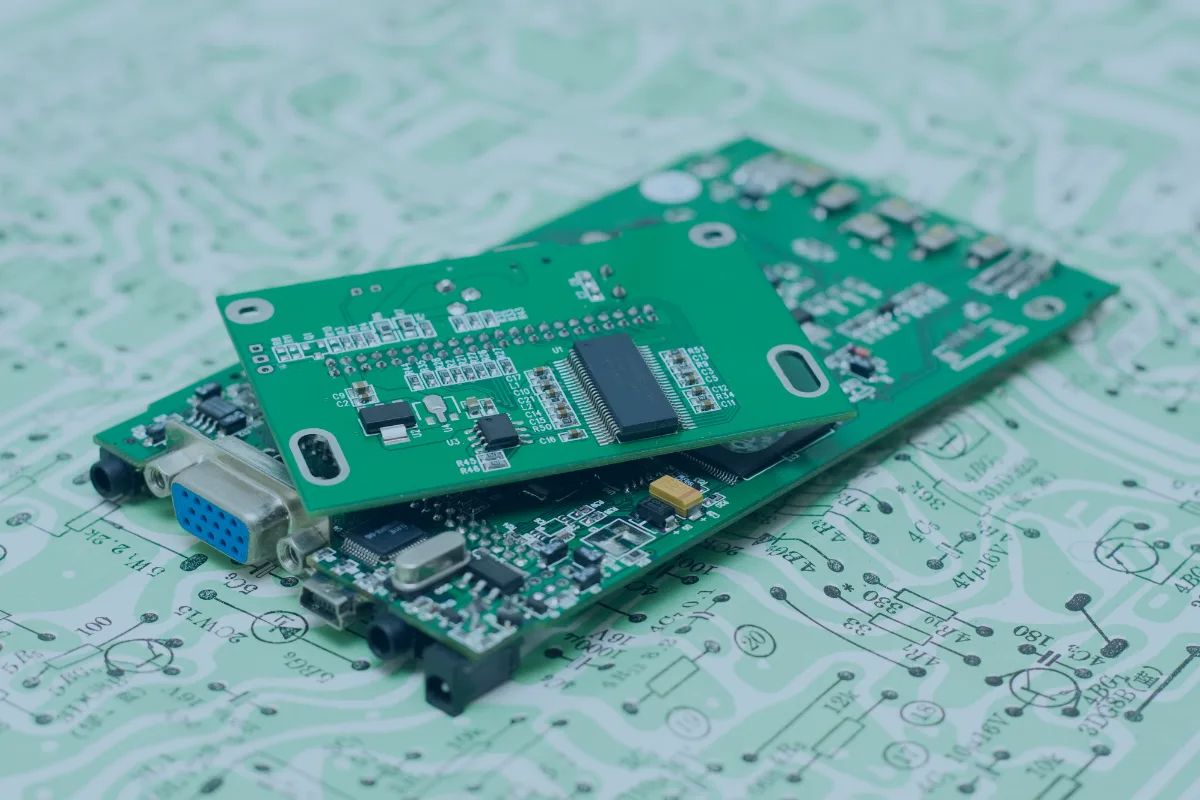
What Is a Printed Circuit Board?
A printed circuit board is an electronic assembly that utilizes copper conductors (alternating layers of conductive copper with layers of insulating material) to create electrical connections between a variety of components. Electronic components are mounted on a board, and traces connect the circuit board components together to form a working circuit or assembly.
What Is PCB Design?
This is the process of creating the physical PCB layout that connects electronic components through copper pathways on a rigid board. Engineers use specialized design software (such as Altium or KiCad) to plan how these conductive layers, insulating materials, and components come together.
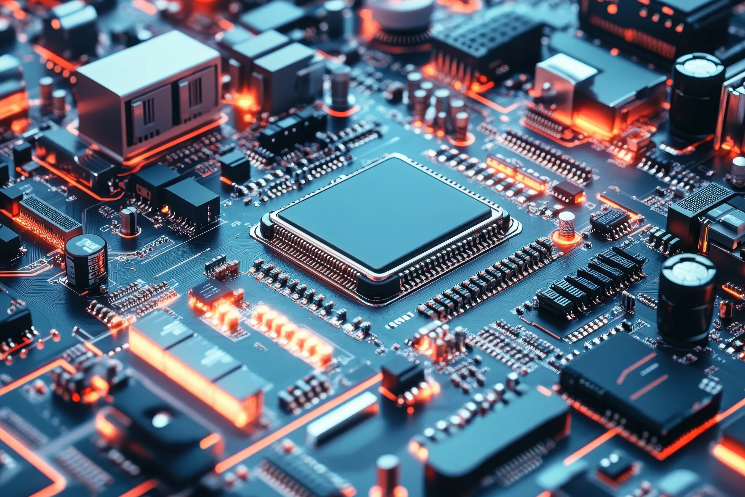
A Printed Circuit Board can be:
- Single-sided: one copper layer on one side of a substrate
- Double-sided: copper layers on both sides of a substrate
- Multilayer PCB: multiple layers of copper alternating with substrate, used for advanced circuits and compact designs
By combining precision design with advanced manufacturing, PCBs ensure reliable performance, efficient power delivery, and long-term durability for electronic systems.
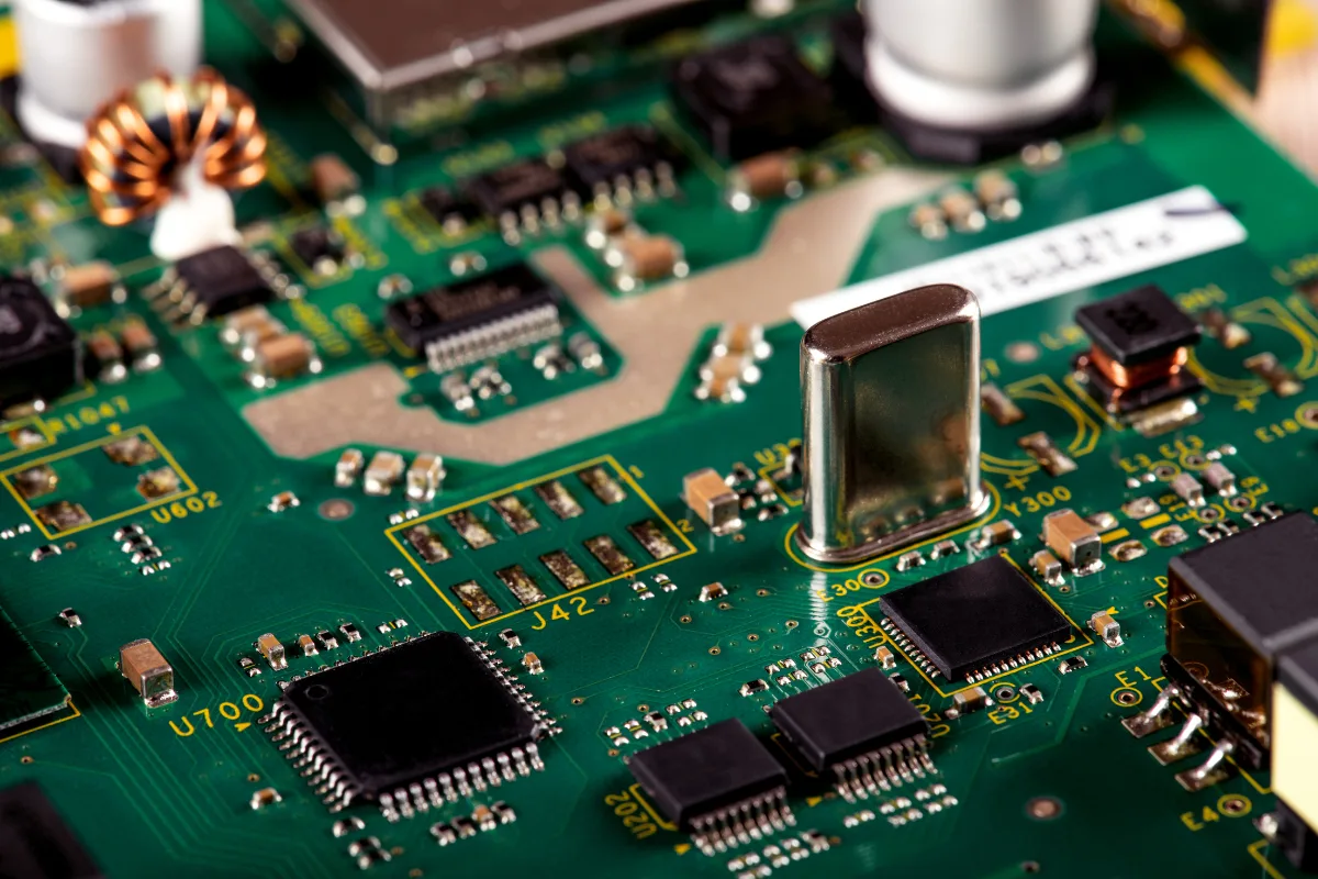
What are the components of a PCB?
Printed Circuit Boards are made up of a variety of electrical components. Each component is essential to the function of the device, ensuring smooth operation.
→ Resistors are one of the most commonly used circuit board components. They control electric current flow, producing voltage drops and dissipating electric power as heat. Traditional through-hole resistors feature axial leads and colour-coded bands indicating their resistance values. However, modern surface-mount technology (SMT) resistors are tiny rectangular packages—some as small as 0.01″ x 0.005″—with resistance values printed directly on the component rather than indicated by colour codes.
→ Capacitors are the second most common component in a PCB. They hold electrical charge (electrostatic energy) and release it when more power is needed in the circuit. They generally accomplish this by collecting opposite charges on two conductive layers that are separated by an insulating material. Though there are many types of capacitors (high-capacity electrolytic, diverse polymer, ceramic disc, etc.), the classic radial style with two leads protruding from the same end is the most common.
→ Transistors are amplifiers that switch/control electronic signals in a PCB and are a fundamental building block of electronics. The most common is a bipolar transistor composed of three pins (base, collector, and emitter). There are three main types of transistors:
- NPN-type transistors involve a small current flowing through the base to the emitter, turning on another circuit that causes a larger current to flow from the collector to the emitter.
- PNP transistors reverse this process.
- FETs use an electric field to activate another circuit.
→ Inductors store energy in the form of a magnetic field, generated when current flows through. They’re essentially a coil of wire; the greater the number of windings, the greater the magnetic field. Inductors are used to filter and/or block signals within the PCB.
→ Transformers transfer electrical energy from one circuit to another, increasing or decreasing voltage. They consist of a soft iron core with coils of wire wound around. The primary coil is for the source circuit, and the secondary coil is for the circuit the energy is being transferred to.
→ Diodes allow electrical current to flow in one direction only, providing zero resistance in one direction and high resistance in the other. They’re used to block current from flowing in the wrong direction, causing damage to the board/device.
→ Sensors detect changes in environmental conditions (light, humidity, air quality, sound, motion, moisture, etc.) and generate an electrical signal that corresponds to that change. The signal is then sent to the other circuit board components.
→ Silicon Controlled Rectifiers (SCRs) involve two transistors working together. They have three leads and four silicon layers and function as switches, not amplifiers, making them suited for switching large amounts of power. A single pulse activates the switch.
→ Integrated Circuits (ICs) are circuits/components that are made of thin wafers of semiconductor material. They’re the brains of a wider circuit, are encased in a black plastic housing, have visible contacts (leads, contact pads), and come in all shapes and sizes. Their diminished profile allows great numbers to be fit onto a single chip.
→ Crystal oscillators are the timing devices for circuits that require precise and stable timing elements. They make electronic signals by causing a crystal to oscillate at a specific frequency. They’re stable, economical, and small compared to other timing devices. Crystal oscillators are used as precise timers for microcontrollers.
→ Switches are power buttons that control current flow in a circuit by switching between an open and closed circuit. They can be slider, rotary, push button, lever, toggle, and/or key switches.
→ Relays are electromagnetic switches operated via a solenoid. They work as a switch and also amplify currents.
Without these various components, circuit boards would not be fully optimized to attain all their possible potential.
How Is a PCB Designed?
Software aids designers in progressing through a specific process for circuit board design, beginning with basic electrical drawings and ending with manufacturing file preparation. There are a number of steps involved in the designing of a printed circuit board.
Step 1. Setting the parameters
It’s important to know/understand the parameters of the system, such as:
- Current maximums
- Voltages
- Signal types
- Capacitance limitations
- Impedance characteristics
- Shielding considerations
- Physical size, dimensions, and mounting requirements
- I/O access and connector placement
- Type and location of circuit components and connectors
- Detailed net wire listing and schematic
Step 2. Creating the schematic
This is the design of the electrical level of the printed circuit board’s purpose and function.
Step 3. Creating the layout
At this stage, engineers develop the layout using a software platform. This graphic shows how the board will physically be arranged and where components will be located. The design is loaded, and the engineer determines how it will fit in the device.
Step 4. Designing the stack-up
Involves determining the arrangement of copper and insulation layers. The stack-up affects how the engineer can design and fit the PCB into the device.
Step 5. Defining design rules/requirements
IPC standards dictate electronics manufacturing, informing engineers of standards/criteria of acceptability and determining design. They are taken into account at this stage of PCB design and development.
Step 6. Placing components
The designer locates components on the board based on electrical requirements, thermal considerations, and mechanical constraints. Component placement directly affects signal integrity, thermal management, and manufacturability. This critical design step is sent to the customer for approval before moving forward.
Step 7. Routing the traces
Once components are placed, the designer determines the best routes to complete each electrical connection. Traces on a PCB carry very specific design requirements that ensure signal integrity. These conductive pathways connect components on the surface layer and between internal layers. Routing techniques used for a PCB depend on the signalling standard you’re working with and the required routing topology. Drill holes and vias are defined as part of this routing process to enable connections between layers.
Step 8. Adding labels/identifiers
These reference designators show where specific components are located on the board and are essential for traceability during production, assembly, and after-sales distribution. They enable manufacturers to integrate the right units into products.
Step 9. Generating design/layout files
The final step in designing a PCB involves files that contain pertinent information. Once these files are generated, the Printed Circuit Board is ready for fabrication, manufacturing, and assembly.
Designing and manufacturing a printed circuit board is a complex process involving many steps, materials, and composition practices. This is where quality control processes become essential to ensure every board meets specifications and performs reliably in its intended application.
When to Partner with an EMS for PCB Design and Manufacturing
While understanding PCB design fundamentals is valuable, knowing when to involve an electronic manufacturing services partner can make the difference between a product that’s designed well and one that’s designed for efficient, cost-effective production.
Many companies discover manufacturing challenges too late in the development process—after prototypes are built, tooling is ordered, or production has already begun. Issues like component placement that complicates assembly, trace routing that increases manufacturing time, or design choices that limit material options can significantly impact both cost and timeline.
Bringing an EMS partner into the conversation early helps prevent these costly surprises. Experienced manufacturers can review your design with an eye toward design for manufacturability, identifying potential issues before they become expensive problems. This includes evaluating component availability and lead times, optimizing board layouts for efficient assembly, recommending material choices that balance performance with cost, and planning for testing and quality verification processes.
The benefits of early collaboration extend beyond avoiding problems. When your manufacturing partner understands your product goals from the beginning, they can suggest improvements you might not have considered—alternative components that offer better availability, layout modifications that speed up assembly time, or testing strategies that catch issues before they reach production scale.
This integrated approach is particularly valuable for companies moving from prototype to production. The transition from building a few boards to manufacturing hundreds or thousands requires different considerations around component sourcing, assembly processes, and quality assurance. An experienced EMS partner helps bridge that gap, ensuring your design translates smoothly from concept to commercial reality.
At IMS, our approach combines electronics expertise with integrated manufacturing capabilities. Because we handle both PCB assembly and custom enclosure fabrication under one roof, we can optimize your entire product—not just the circuit board. This means better coordination between electrical and mechanical design, faster turnaround times, and a single point of contact throughout your project.
Whether you’re developing your first prototype or scaling an existing product, talking with our engineering team early in the design phase can save significant time and cost down the road. We work collaboratively with your team to ensure your PCB design is optimized for performance, manufacturability, and long-term success.
Ready to discuss your next PCB design project?
Our team can review your design for manufacturability and help you avoid common production pitfalls. Contact our team today to talk about how we can support your electronics manufacturing needs.
IMS Electronics serves companies across industries with in-house manufacturing capabilities and state-of-the-art equipment. Let us be your partner for custom electronic manufacturing and metal fabrication services. We also happily support customer-specific requirements.